UART INTERFACING WITH ARDUINO
This tutorial discuss how to interface UART with Arduino. Serial communication allows sending and receiving data or commands between the computer and control board. In this project, we will be sending a data from the Arduino and it will be serially printed on the virtual terminal.
Synopsis

Arduino boards all have a serial port that connects to the USB device port on the board. This port allows sketches to be loaded to the board using a USB cable. Code in a sketch can use the same USB / serial port to communicate with the PC by using the Arduino IDE Serial Monitor window, or a Processing application for example. The USB port appears as a virtual COM port on the PC.

This tutorial discuss how to interface UART with Arduino. Serial communication allows sending and receiving data or commands between the computer and control board. In this project, we will be sending a data from the Arduino and it will be serially printed on the virtual terminal.

Description

UART stands for Universal Asynchronous Receiver/Transmitter. It’s not a communication protocol like SPI and I2C, but a physical circuit in a microcontroller, or a stand-alone IC. A UART’s main purpose is to transmit and receive serial data. One of the best things about UART is that it only uses two wires to transmit data between devices. The principles behind UART are easy to understand.

All Arduino boards have at least one serial port (also known as a UART or USART). It communicates on digital pins 0 (RX) and 1 (TX) as well as with the computer via USB.

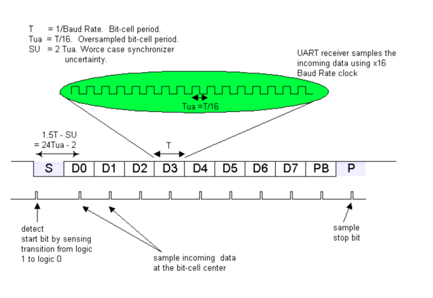
Asynchronous transmission allows data to be transmitted without the sender having to send a clock signal to the receiver. In this case, the sender and receiver must agree on timing parameters (Baud Rate) prior transmission and special bits are added to each word to synchronize the sending and receiving units. In asynchronous transmission, the sender sends a Start bit, 5 to 8 data bits (LSB first), an optional Parity bit, and then 1, 1.5 or 2 Stop bits.

When a word is passed to the UART for asynchronous transmissions, the Start bit is added at beginning of the word. The Start bit is used to inform the receiver that a word of data is about to be send, thereby forcing the clock in the receiver to be in sync with the clock in the transmitter. It is important to note that the frequency drift between these two clocks must not exceed 10%. In other words, both the transmitter and receiver must have identical baud rate.

After the Start bit, the individual bits of the word of data are sent, beginning with the Least Significant Bit (LSB). When data is fully transmitted, an optional Parity bit is sent to the transmitter. This bit is usually used by receiver to perform simple error checking. Lastly, Stop bit will be sent to indicate the end of transmission.

When the receiver has received all of the bits in the data word, it may check for the Parity Bits (both sender and receiver must agree on whether a Parity Bit is to be used), and then the receiver searches for a Stop Bit. If the Stop Bit does not appear when it is supposed to, the UART considers the entire word to be garbled and will report a Framing Error to the host processor when the data word is read. Common reason for the occurrence of Framing Error is that the sender and receiver clocks were not running at the same speed, or that the signal was interrupted.


Every operation of the UART hardware is controlled by a clock signal which runs at much faster rate than the baud rate. For example, the popular 16450 UART has an internal clock that runs 16 times faster than the baud rate. This allows the UART receiver to sample the incoming data with granularity of 1/16 the baud-rate period and has greater immunity towards baud rate error.

The receiver detects the Start bit by detecting the voltage transition from logic 1 to logic 0 on the transmission line. In the case of 16450 UART, once the Start bit is detected, the next data bit’s “center” can be assured to be 24 ticks minus 2 (worse case synchronizer uncertainty) later. From then on, every next data bit center is 16 clock ticks later.


Transmitting and receiving UARTs must be set at the same baud rate, character length, parity, and stop bits for proper operation. The typical format for serial ports used with PC connected to modems is 1 Start bit, 8 data bits, no Parity and 1 Stop bit.

ADVANTAGES:

• Only uses two wires.

• No clock signal is necessary.

• Has a parity bit to allow for error checking.

• The structure of the data packet can be changed as long as both sides are set up for it.

• Well documented and widely used method.

Proteus design for UART interfacing with Arduino


Orcad design for UART interfacing with Arduino


Proteus design for UART interfacing with Arduino


Orcad design for UART interfacing with Arduino


UART interfacing with Arduino

/* Name    : main.c
* Purpose  : Source code for UART Interfacing with Arduino.
* Author   : Gemicates
* Date     : 09-02-2018
* Website  : www.gemicates.org
* Revision : None
*/

#include <SoftwareSerial.h>

                                                                         // These constants won't change.  They're used to give names
                                                                         // to the pins used:
const int TX = 3;                                                        // Transmit
const int RX = 2;                                                        // Receive

SoftwareSerial myserial(RX, TX);


void setup() 
{
  
  Serial.begin(9600);
  while (!Serial) 
  {
    ;                                                                    // wait for serial port to connect. Needed for native USB port only
  } 
  
  myserial.begin(9600);                                                  // initialize serial communications at 9600 bps
  
  Serial.println("GEMICATES LABS");
}

void serialEvent()
{
  String TXData = Serial.readStringUntil('\n');
  
  if (TXData.length())
  {
    Serial.println("");
    Serial.print("<- ");
    Serial.print(TXData);
    Serial.println("");
    myserial.print(TXData);
  }
}

void loop() {
  myserial.listen();
  
                                                                         // Receive data
  while (myserial.available() > 0)
    Serial.write(myserial.read());
}
Error message here!

Show Error message here!


Forgot your password?

Error message here!

Send OTP

Error message here!

Show Error message here!


Lost your password? Please enter your email address. You will receive a password you Need.

Send Error message here!


Back to log-in

Close